Motion Laws
According to Wikipedia,
Movement in a physical sense is the change of the location of an observed object over time.
Sir Isaac Newton formulated 1687 three basic motion laws, simplified:
1) Bodies remain at rest or move at constant speeds when no force acts on them
2) Force equals mass times acceleration
3) Pulling forces equal pushing forces
Motion laws are laws by which bodies move.
In case of cam gears, the movements are actually "set" because you specify the desired movements in order to obtain the cam tracks. Cam tracks result from movements.
In German-speaking countries, the VDI Guideline 2143, specifically Sheet 1 (released in October 1980), has been something of a "bible" for cam technicians for decades. Our founder, Günther Nolte, was a member of the committee that set up the VDI Guideline 2143.
This guideline is like reading a formula collection for motion laws. It says:
"Motion laws are analytical functions that describe the relative movement of two mechanism parts, in most cases the output movement of cam gear as a function of the driving motion."
In case of cams, motion laws describe the characteristic of the dependence of the output variable (oscillation angle, carriage travel, etc.) over the input variable (eg cam rotation angle) with respect to a single movement segment. Analogously, this applies to servo drives for the master as the input variable and the slave as the output variable.
"Characteristic" here means that the transfer function of the cam gear is normalized.
Motion laws are normalized transfer functions.
Normalization means that the driving parameter z runs through the value range 0 to 1 in a motion section, and that for the normalized transfer function f in this section applies: f (0) = 0 and f (1) = 1.
Motion laws depict motion characteristics and decisively decide which forces, moments, pressures and natural vibrations occur in a cam mechanism or mechanism, or just do not occur. By selecting and fine-tuning motion laws, you have an influence on the performance of your machines.
Therefore, from our point of view, it is very important to have many motion laws and fine-tuning techniques to fully exploit the potential of the cam and servo controlled machines.
When the VDI guideline was released in 1980, "motion design" was often used in companies to specify the Modified Sine or Fifth-order Polynomial as the factory standard.
That's not sufficient today!
Our software OPTIMUS MOTUS offers a lot of motion laws, more by number and more varied than we have seen anywhere else in a heap. A little further on this page they are listed.
Many of these items, however, not just offer a single motion law, but a whole design methodology actually. These methodologies, quasi-designable motion laws, make motion design with OPTIMUS MOTUS really powerful.
OPTIMUS MOTUS offers motion laws and motion design into an easy-to-use graphical editor, which conceals the actual complexity of motion design as far as possible.
Skip to ...
- Terms
- Motion law list
- Characteristic values
- Cycloidal Motion / Inclined Sine
- Polynom 5th degree
- Modified Trapezoidal
- Modified Sine
- Inflection point shift
- Emulation of sinusoidal motion laws
- scca motion laws
- Training and Know How
- Software
- Calculation
Terms
For planning, motion sequences cam or servo controls are shown schematically in the form of displacement plans:
In complex motion controls, displacement plans contain many such schematic curves that are synchronized over time or a common driving parameter. We use the time parameter phi for this synchronization.
At some point in motion design of course you must select a motion characteristic, a motion "law" for each motion section. That transforms a "displacement plan" into a "motion diagram".
A normalized motion law f(z) describes the relation between input and output quantities for a mechanism in one motion section.
The normalization is that the driving parameter z in this section goes from 0 to 1 and that f(0) = 0 and f(1) = 1.
Beginning or end of a motion section are referred to as "boundary positions". These are the times between two motion sections.
f(z) = normalized motion law, normalized path function, normalized transfer function
f'(z) = 1st derivation according to the normalized driving parameter z (normalized velocity, normalized motion law 1st order)
f''(z) = 2nd derivation according to the normalized driving parameter z (normalized acceleration, normalized motion law 2nd order)
f''(z) = 3rd derivation according to the normalized driving parameter z (normalized jerk function, normalized motion law 3rd order)
f‘(z) • f‘‘(z) = power characteristic (with respect to inertial output mass) in the normalized motion law
Note:
f’ • f’’ actually is the mass-related performance in normalized form.
With
P = M • w = m • v • a = F • v
for an inertial mass m results
M ~ v • a ~ f’ • f’’
at constant drive angular velocity w and constant mass m.
Then the shape of f’ • f’’ qualitatively corresponds to the drive torque cam M at the drive.
The VDI Guideline 2143 defines four states of motion for the boundary positions:
R = Dwell (f'=0 und f''=0)
U = Return (f'=0)
G = Straight Line (f''=0)
B = General Motion (arbitrary values for f' and f'')
Motion laws describe a transition from an initial state of motion to an end state of motion. For example, a motion law of type RR starts with a dwell state (f'(0) = 0 and f''(0) = 0) and ends in a dwell state (f'(1) = 0 and f'' (1) = 0) ). All RR motion laws are summarized in one chapter of VDI Guideline 2143. Other chapters describe transitions RU (return-to-return), UU (return-to-return), BB (motion-in-motion), and so on.
If one sets motion sections improperly one behind the other, jumps in the speed, so-called "shocks", or in the acceleration, so-called "jerks" arise.
A shock is a speed jump. Shocks are very damaging to the mechanics, even at low speeds. They cause wear, noise and large following errors in servo drives.
A jerk is a jump in acceleration. The value of the jerk function f'''(z) is infinitely large. Jerks usually cause disturbing natural oscillations in the mechanism at medium and especially at higher speeds. In general, the basic requirement in cam technology is that movements should be made jerk-free.
Jerks can be acceptable in exceptional cases, if the motion design has other advantages and the mechanics are so stiff that natural oscillations will not harm.
Shocks and jerks on boundary positions of the type U, G or B are avoided by means of the boundary value adjustment.
Commonly used is the inflection point shift described in the VDI Guideline 2143 as a transformation with the parameter lambda in order to vary movement segments, see the following figure.
lambda denotes the driving parameter z, at which the sign of the acceleration changes. For a non-transformed motion law is lambda = 0.5. Often the acceleration and deceleration phases of an untransformed motion law are similar. Then it is "symmetrical".
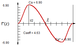
For the selection of a motion law suitable for the motion task, the characteristic values of the motion law are often used (see picture):
CMdyn = dynamic power parameter
CMstat = static power parameter
Ca = characteristic value of the normalized acceleration
Ca* = characteristic value of the normalized acceleration
Cv = characteristic value of the normalized speed
Cj = characteristic value of the normalized jerk function
CMeff = characteristic value of the normalized effective power
Caeff = characteristic value of the normalized effective acceleration
Motion laws are preferred whose characteristic value profiles fit best to the dynamic properties of the mechanics.
In a servo drive with a very rigid coupling of the load, for example, the Polynomial 8th degree works quite well, or else the Modified Trapezoidal.
If it is necessary to avoid natural oscillations, usually the Polynomial 7th degree is fine.
A little further in the text you will find tables with characteristic values of motion laws.
List of Motion Laws:
The software OPTIMUS MOTUS offers the following motion laws:
1 Linear Dwell
2 Circular Dwell
3 Cycloidal Motion
4 Polynomial 5th degree
5 Modified Trapezoidal
6 Modified Sine
7 Simple Sine
8 General Cycloidal Motion
9 Harmonic Motion Law
10 Polynomial 5th degree with Straight Line
11 Polynomial 11th degree
12 Squared Parabola
13 Modified Sine G-G
14 Sine-Straight line-combination U-U
15 Modified Trapezoidal R-U
16 Harmonic Combination R-U
17 Harmonic Combination G-U
18 Polynomial 5th degree B-B
19 Straight Line
20 Modified Trapezoidal U-U
21 Spline
22 Cubic splines
23 Acceleration Polygon Type A-C
24 Modified Harmonic Combination Type A
25 Modified Harmonic Combination Type B
26 Trigonometric Cos-Splines
27 Law M1
28 Polynomial 8th degree
29 General Acceleration Polygon
30 Low-noise Cosine Combination
31 Polynomial 3rd degree
32 Polynomial 4th degree
33 Polynomial 6th degree
34 Polynomial 7th degree
35 Polynomial max. 20th degree with Coefficients
36 Polynomial max. 20th degree with Constraints
37 Value Table
38 Mirrored Sine
39 Fourier series
40 Constant Value 1
41 Modified Sine with Straight Line R-R
42 Synchronous Operation
43 Modified Harmonic Combination Type C
44 Modified Harmonic Combination Type D
45 Table for Dwell-to-Dwell-Transitions
46 General Sinus Combination
47 Double Harmonics
48 Energy saving polynomial 1
49 Energy saving polynomial 2
50 Polynomial 15th degree
51 Freudenstein 1-3
52 Gutman F-3
53 Berzak D
54 Berzak E
55 Peisekah 11th degree
56 Polynomial Splines
57 Polynomial 7th degree type A
58 Polynomial 13th degree
59 HS Motion Law dwell-to-dwell
60 YMS-3
61 YCMV-3
62 YHP-5
63 SMS-3
64 SMCV-3
65 SMT-3
Some of these motion laws are defined throughout, ie with one functional term for the entire value range of the parameter z. Other motion laws are composed of subsections and thus defined with multiple functional terms, one for each subsection.
Most of the listed motion laws have no further parameters. Others, however, have some or even many additional parameters, so the term "motion law" does not really fit anymore. These would rather have to be called "motion design methods".
The detailed discussion of all these motion laws would definitely go beyond the scope of this page.
But some motion laws are so basic that we want to describe them in more detail:
- Cycloidal Motion / Inclined Sine (including derivation)
- 5th degree Polynomial (including derivation)
- Modified Trapezoidal
- Modified Sine
This does not imply that these motion laws were particularly "good". They simply belong to the basic repertoire of every cam technician and therefore deserve a detailed description.
To make machines fast, of course, we dig deeper into the bag of tricks ;-)
For questions about individual motion laws please call us!
Bei Fragen zu einzelnen Bewegungsgesetzen rufen Sie uns bitte an!
We like to share our know-how with you in seminars on cam design, motion design and motion laws in particular.
Characteristic values
To compare dwell-to-dwell motion laws directly, we provide a table with characteristic values. The number at the beginning of each line is the motion law number from OPTIMUS MOTUS (see above):
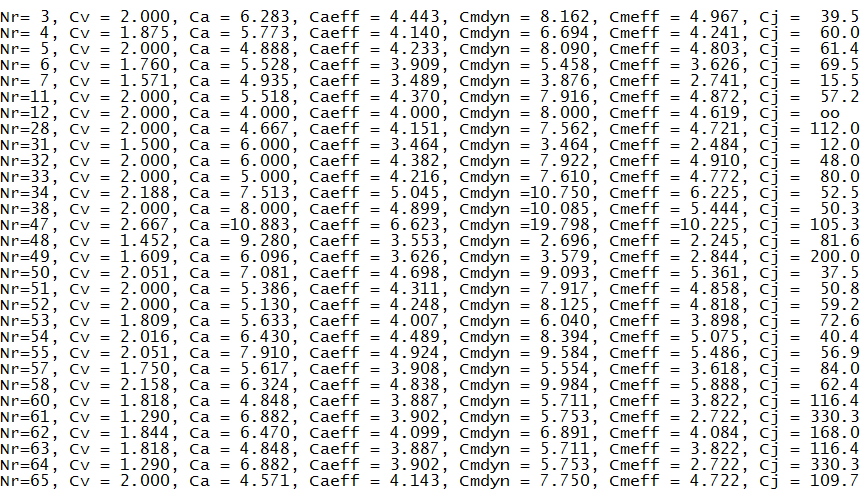
With these characteristic values you see how speed (Cv), acceleration (Ca, Caeff), jerk function (Cj) and dynamic torque (Cmdyn, Cmeff) of two motion laws with the same stroke and the same transition time differ.
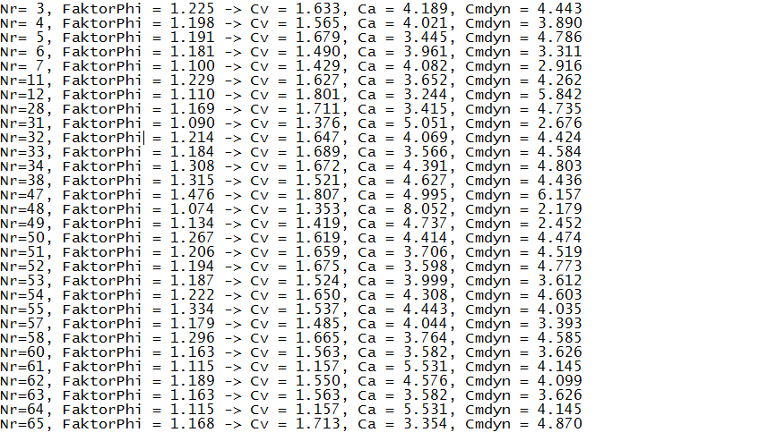
However, this comparison is not quite fair if - as is usually permissible in practice - one can exploit small tolerances.
Therefore, we have given here a second table with the characteristics for Cv, Ca and Cmdyn in the event that at the beginning of the defined motion section already 0.5% of the stroke may be passed through and at the end of the section 0.5% remaining way may be left. At a stroke of 100mm, this corresponds to a tolerance of 0.5mm, which is very often allowed in practice. This table therefore takes into account a range extension.
FaktorPhi is the factor by which the motion section on the time axis can be stretched until the tolerance is exploited. This is also the factor by which you can run the cam gear faster, allowing the same dynamic loads as in the case without range extension.
The characteristics Cv, Ca and Cmdyn of the following table correspond to the velocity, acceleration and moment values of the range-extended motion section with respect to the length of time of the non-range-extended section. By comparing with the first table, you can see directly how speed, acceleration and dynamic torque go back by extending the time for the motion section.
Characteristic values of the dwell-to-dwell motion laws in OPTIMUS MOTUS, considering range extension with a tolerance of 0.5% of the stroke:
Cycloidal Motion / Inclined Sine
One of the best known motion laws is the Cycloidal Motion (also called "Inclined Sinus") according to Helling-Bestehorn.
We do not use it frequently because of the high maximum acceleration. In the VDI guideline it is the "smoothes" RR motion law. But if we want to make smooth movements, we prefer to use other, more effective methods.
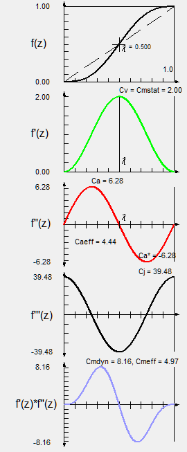
The following figure shows on the right the diagrams of path, speed, acceleration, jerk function and torque (mass-related power actually) of the normalized motion law, including the characteristic values.
The Cycloidal Motion can be derived as follows:
Polynom 5. Grades
A well-known dwell-to-dwell motion law is the 5th degree polynomial, also called the 5th order polynomial or 3-4-5 polynomial.
It has always been popular with cam calculators and is also very popular in the world of servo drives. The main merit is that it is easy to deduce and generally applicable in the case of motion-to-motion.
The 5th degree polynomial is not very good in any criterion, but not very bad either. It has a balanced profile of characteristic values and could be described as a "decathlete" among the motion laws.
The following figure shows on the right the diagrams of path, speed, acceleration, jerk function and mass-related power of the normalized motion law, including the characteristic values.
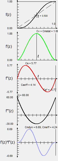
Here is the derivation of the polynomial 5th degree dwell-to-dwell:
Modified Trapezoidal
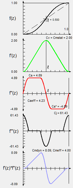
The Modified Trapezoidal or "Trapezoidal" is characterized by its low maximum acceleration in the absence of jerks.
It is used in servo technology to keep both the maximum and the effective drive torques small. In mechanical cams it improves the radius of curvature and helps to avoid undercut.
The following figure shows on the right the diagrams of path, speed, acceleration, jerk function and mass-related power of the normalized motion law, including the characteristic values.
Modified Sine
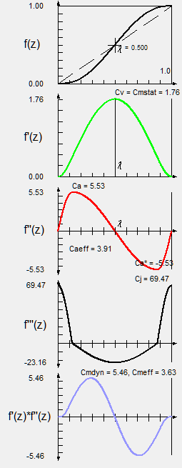
The Modified Sine by Neklutin is characterized by relatively low velocity, acceleration and power values, but has high jerk function values.
It is used very often, also with straight drawers, in indexing gears to produce stepping motions.
Because of the high jerk function values, however, such indexing gears tend to cause vibrations (residual oscillating motions) in the dwell phase. If you want to use an indexing mechanism to move elastic mechanisms with a small natural frequency, for example long, heavy chains, you should prefer other motion laws.
Inflection point shifting
With normalized motion laws f(z), the driving parameter z runs from 0 to 1.
Symmetrical normalized motion laws fs with the property fs(0.5) = 0.5 (half stroke after half time) can be subjected to a transformation with a parameter lambda, called the inflection point shift:
The inflection point parameter lambda is between 0 and 1.
With lambda = 0.5 you have a symmetric motion law. This is the standard case.
With the inflection point shift, the shape of an acceleration curve can be changed. If the inflection point is shifted toward the end of the section (lambda > 0.5), the maximum acceleration decreases in the range between 0 and lambda, and the acceleration increases in the range from lambda to 1.
If the inflection point is shifted toward the section start (lambda < 0.5), the maximum acceleration increases in the range between 0 and lambda, and the acceleration decreases in the range from lambda to 1.
If lambda is very close to 0 or 1, you suffer very high accelerations. Therefore, we recommend to keep the inflection point in the range between 0.3 and 0.7.
The maximum speed in a motion section does not change due to the inflection point shift.
Inflection point shifting can be used to pass through a required control point that is not very far from the symmetric motion law.
By distorting the acceleration, you also use it to make the beginning or end of a motion section smoother.
An example of an inflection point shift shows the following picture with the inflection point parameter lambda = 0.3:
Emulation of sinoidal motion laws
(Service for users of the software OPTIMUS MOTUS)
The following table shows how to emulate well-known sinusoidal motion laws with more general motion laws in OPTIMUS MOTUS, each without straight line insertion and without inflection point parameters:
No. 3, Cycloidal Motion / Inclined Sine:
Emulatable with motion law 9: p1 = p2 = p4 = p5 = 0.25, p3 = 0.
Emulatable with motion law 24: c1 = c2 = 0.25, c3 = c4 = 0.5, c5 = c6 = 0.75
Emulatable with motion law 46: c1 = c2 = 0.25, c3 = c4 = 0.5, c5 = c6 = 0.75, Type1 = Type2 = Type3 = Type4 = 2
No. 5, Modified Trapezoidal:
Emulatable with motion law 24: c1 = 0.125, c2 = 0.375, c3 = c4 = 0.5, c5 = 0.625, c6 = 0.875
Emulatable with motion law 46: c1 = 0.125, c2 = 0.375, c3 = c4 = 0.5, c5 = 0.625, c6 = 0.875, Type1 = Type2 = Type3 = Type4 = 2
No. 6, Modified Sine:
Emulatable with motion law 9: p1 = 0.125, p2 = 0.375, p3 = 0, p4 = 0.375, p5 = 0.125
Emulatable with motion law 24: c1 = c2 = 0.125, c3 = c4 = 0.5, c5 = c6 = 0.875
Emulatable with motion law 46: c1 = c2 = 0.125, c3 = c4 = 0.5, c5 = c6 = 0.875, Type1 = Type2 = Type3 = Type4 = 2
No. 7, Simple Sine:
Emulatable with motion law 9: p1 = 0, p2 = 0.5, p3 = 0, p4 = 0.5, p5 = 0
Emulatable with motion law 24: c1 = c2 = 0, c3 = c4 = 0.5, c5 = c6 = 1
Emulatable with motion law 46: c1 = c2 = 0, c3 = c4 = 0.5, c5 = c6 = 1, Type1 = Type2 = Type3 = Type4 = 2
No. 12, Squared Parabola:
Emulatable with motion law 24: c1 = 0, c2 = c3 = c4 = c5 = 0.5, c6 = 1
Emulatable with motion law 46: c1 = 0, c2 = c3 = c4 = c5 = 0.5, c6 = 1, Type1 = Type2 = Type3 = Type4 = 1
No. 23, Acceleration Polygon Type A:
Emulatable with motion law 46: c1 = 0.05, c2 = 0.25, c3 = c4 = 0.5, c5 = 0.75, c6 = 0.95, Type1 = Type2 = Type3 = Type4 = 1
Shares of straight line with motion law number 9:
p3 = (straight line insertion in% time component) / 100
The parameters p1, p2, p4 and p5 from the motion law without straight line insertion according to the above table are multiplied by the factor (1-p3).
Shares of straight line with the motion laws numbers 24, 25, 43, 44 and 46:
Ci* = parameters from the motion law without straight line insertion according to the table above
Ci = parameters from the motion law with straight line insertion
g = c4 - c3 = (straight line insertion in percent time component) / 100
c1 = c1* • (1 - g)
c2 = c2* • (1 - g)
c3 = c3* • (1 - g)
c4 = 1 - (1 - c4*) • (1 - g)
c5 = 1 - (1 - c5*) • (1 - g)
c6 = 1 - (1 - c6*) • (1 - g)
scca Motion Laws
(Service for users of the software OPTIMUS MOTUS)
Outside the OPTIMUS MOTUS software, the term "scca motion law" is used for a particular family of sine combinations.
Such motion laws can be reproduced in OPTIMUS MOTUS with motion law number 24 (Modified Harmonic Combination Type A).
SCCA motion laws are described by four parameters a, b, c, d with
a + b + c + d = 1
Of these, only three parameters must be given, as the fourth results from the above equation.
Motion law 24 (Modified Harmonic Combination Type A in OPTIMUS MOTUS) uses instead the normalized time parameters c1, c2, c3, c4, c5, c6.
The values of these parameters ci can be calculated from the scca parameters as follows:
c1 = a / 2
c2 = c1 + b / 2 = a / 2 + b / 2
c3 = c2 + c / 2 = a / 2 + b / 2 + c / 2
c4 = c3 + d = 1 - a / 2 - b / 2 - c / 2
c5 = c4 + c / 2 = 1 - a / 2 - b / 2
c6 = c5 + b / 2 = 1 - a / 2
With an asymmetry factor e (= inflection point parameter lambda), the symmetric motion law can be subsequently modified.
The symmetric motion law is characterized by e = lambda = 0.5.
Depending on e, the parameters c1..c6 of the symmetric motion law (lambda = e = 0.5) change as follows for the unbalanced motion law:
c1e = c1 · 2 · e
c2e = c2 · 2 · e
c3e = c3 · 2 · e
c4e = 1 – (1 – c4) · 2 · (1 – e)
c5e = 1 – (1 – c5) · 2 · (1 – e)
c6e = 1 – (1 – c6) · 2 · (1 – e)
Examples:
MS (Modified Sine):
a = 0.25, b = 0, c = 0.75 results in c1 = c2 = 0.125, c3 = c4 = 0.5, c5 = c6 = 0.875
MSC 15 (Modified Sine with 15% straight line insert):
a = 0.2125, b = 0, c = 0.6375 results in c1 = c2 = 0.10625, c3 = 0.425, c4 = 0.575, c5 = c6 = 0.89375
MSC 20 (Modified Sine with 20% straight line insert):
a = 0.2, b = 0, c = 0.6 results in c1 = c2 = 0.1, c3 = 0.4, c4 = 0.6, c5 = c6 = 0.9
MSC 25 (Modified Sine with 25% straight line insert):
a = 0.1875, b = 0, c = 0.5625 results in c1 = c2 = 0.09375, c3 = 0.375, c4 = 0.625, c5 = c6 = 0.90625
MSC 33 (Modified Sine with 33% straight line insert):
a = 0.1666, b = 0, c = 0.5 results in c1 = c2 = 0.08333, c3 = 0.33333, c4 = 0.66667, c5 = c6 = 0.91667
MSC 50 (Modified Sine with 50% straight line insert):
a = 0.125, b = 0, c = 0.375 results in c1 = c2 = 0.0625, c3 = 0.25, c4 = 0.75, c5 = c6 = 0.9375
MSC 66 (Modified Sine with 66% straight line insert):
a = 0.08333, b = 0, c = 0.25 results in c1 = c2 = 0.04167, c3 = 0.16667, c4 = 0.83333, c5 = c6 = 0.95833
MT (Modified Trapezoidal):
a = 0.25, b = 0.5, c = 0.25 results in c1 = 0.125, c2 = 0.375, c3 = c4 = 0.5, c5 = 0.625, c6 = 0.875
MTC 50 (Modified Trapezoidal with 50% straight line insert):
a = 0.125, b = 0.25, c = 0.125 results in c1 = 0.0625, c2 = 0.1875, c3 = 0.25, c4 = 0.75, c5 = 0.8125, c6 = 0.9375
SH (Simple Sine):
a = 0, b = 0, c = 1 results in c1 = c2 = 0, c3 = c4 = 0.5, c5 = c6 = 1
CYC (Cycloidal Motion / Inclined Sine):
a = 0.5, b = 0, c = 0.5 results in c1 = c2 = 0.25, c3 = c4 = 0.5, c5 = c6 = 0.75
PAR (Square Parabola):
a = 0, b = 1, c = 0 results in c1 = 0, c2 = c3 = c4 = c5 = 0.5, c6 = 1
To the homepage of Nolte NC-Kurventechnik GmbH
Start Mechanisms Kinematics Software CamDesign Indexing Servo+PLC MotionDesign Training Service CamCalculation Imprint PrivacyPolicy
Terms List CharacteristicValues CycloidalMotion Polynomial5 Trapezoidal ModifiedSine InflectionPoint SineEmulation scca
11/06/21
• Software OPTIMUS MOTUS ® /
DasNolte ®
• All types of Cam Calculations
• Performance Optimizations
• Trainings and consulting
• App and Software Development
• PLC Motion Software
Cams, Mechanisms, Motion Design. Faster Machines. Since 1965.
