Indexing mechanisms, Step gears
Indexing mechanisms ("indexers") convert a continuous input rotation into a stepwise output motion. Between the step motions (the indexing phases), the transmission output is stationary. In most cases the movement at the output is a rotation. The movement at the gearbox output always goes into the same direction. Almost all types of mechanism can generate step-like transmission functions.
Special types of step gears create pilgrim step movements. The movement at the output does not consistently develop in the same direction then, it rather contains small or larger backward movements.
Examples include the rotations in a cam-controlled tool changer or the production of pipes with the pilgrim step method.
Gears normally used to generate step movements can also be modified or designed so that the output produces very general continuous movements without dwells. This enormously extends the application range of the indexing mechanism. Although one can no longer speak of "steps", the indexing mechanism character of the kinematics is retained.
Of particular importance for the practice are the indexing cam gears, especially the parallel indexing cam gear, the cylindrical indexing cam gear and the globoidal indexing cam gear, also servo drives for generating step movements.
In addition, there are a number of other designs, for example, with multiple drives, consisting only of wheels, as a pure linkage and even more special types, which are rarely encountered in practice. Engineers are very ingenious!
We have been specializing in kinematics and cam calculations for decades with all types of indexing drives and would like to assist you with your applications!
Skip to ...
- Glossary
- Calculation
- Indexing cam gears
- Globoidal indexing cams
- Cylindrical indexing cams
- Parallel indexing cams
- Servo controlled step movements
- Geneva drive / Maltese Cross
- Starwheel mechanism
- Cam with revolving lever
- Wheels+linkage
To the homepage of Nolte NC-Kurventechnik GmbH
Glossary
Especially in the most widely used cam-based indexing gears, some technical terms are significant.
Center distance
The most important main dimension in the gearbox from the user's and the manufacturer's point of view: the kinematic distance between the drive axle and output shaft, ie gear input and gear output. Catalogs of indexer manufacturers are usually graded according to the center distance, which determines the size. Other kinematic dimensions, such as the roller diameter, the roller pitch circle diameter or the cam outer diameter, are also of great importance, but really only for design and calculation and thus for the manufacturer.
Plane count
In case of parallel cam gears(CF3 gearboxes), the number of planes is the number of cam disks on the drive link and thus also the number of roller planes on the follower. Parallel gearboxes usually have two levels, but there are also types with three, theoretically even more levels.
Pitch angle
As a rule, the rollers on the follower (the cam driven part) are evenly distributed on a pitch circle diameter. The geometric angle between two rollers is the pitch angle.
Pitch angle = 360 degrees / number of rollers
Number of stops
The number of stops determines after how many steps the gearbox output completes one revolution.
Step number
The step number is the number of steps at the gear output during one revolution at the input.
Double step / N-fold step
In a double step, two steps occur every time the drive shaft rotates. The step number is then 2.
With an N-fold step, N steps occur every full revolution of the drive shaft. The step number is then N.
Step angle
The step angle is the angle that the transmission output passes between the beginning and end of a single step.
Step angle = 360 degrees / stop number
More precisely, the step angle is the incremental angle of two consecutive dwells on the transmission output. At approximate dwells, it refers to the middle dwell position.
The step angle is an integer multiple of the pitch angle. For parallel cam gears, the step angle is also an integer multiple of the plane count.
Indexing angle
The indexing angle is the angle of rotation at the input shaft during an indexing phase. With approximate dwells, one refers to the leaving or the reaching of the middle dwell position.
Dwell angle
The dwell angle is the angle of rotation at the input shaft during a dwell phase (standstill). He can also be 0. Then the output stops only in a moment.
Period angle
The period angle is the smallest drive angle range after which the movements at the gear output are repeated. The period angle does not have to be 360 degrees.
Period angle = 360 degrees / step number
Dwell angle + Indexing angle = Period angle
Input speed
Normally, when designing an indexer, the input shaft rotates at a constant speed, given in rpm (revolutions per minute)
Cycle speed
The cycle speed is the number of indexing / dwell cycles per minute.
Cycle speed = Input speed • Step number
If the cycle speed in the cam calculation program, however, refers to the complete calculation cycle, then
Cycle speed = Input speed
Cycle time
The cycle time is the time used for an indexing / dwell cycle.
Cycle time in s = 60 s / min / (cycle speed in 1 / min)
Cycle time = Indexing time + Dwell time
Indexing time
The indexing time is the time for a single indexing phase.
Dwell time
The dwell time is the time for a dwell phase.
Dwell deviation
In indexing gears with an approximate dwell phase, the dwell deviation is the fluctuation range of the driven positions about the middle dwell position.
Relative dwell deviation
In indexing gears with an approximate dwell phase, the relative dwell deviation is the fluctuation range of the output positions around the middle dwell position, relative to the step angle of the preceding indexing phase. The relative dwell deviation is therefore a relative error and thus a measure of the quality of the dwell.
Dwell period ratio
The dwell-period ratio is the proportion of the dwell on a period related to the drive input angle.
Dwell period ratio = Dwell angle / Period angle = Dwell angle / (Dwell angle + Indexing angle)
If the movement period contains several dwells, all the dwell angles in the movement period are summed up:
Dwell period ratio = (Sum of all dwell angles) / Period angle
Indexing period ratio
The indexing-period ratio is the drive angle portion of the step on a period.
Indexing period ratio = Indexing angle / Period angle = Indexing angle / (Dwell angle + Indexing angle)
If the movement period contains several dwells, all the indexing angles in the movement period are summed up:
Indexing period ratio = (Sum of all indexing angles) / Period angle
Dwell period ratio + Indexing period ratio = 1
Track count
In the case of spatial cam indexing gears (cylindrical indexing cams and globoidal indexing cams) the track count is the number of cam grooves or "tracks" required for motion transmission.
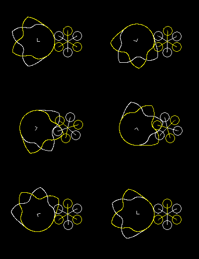
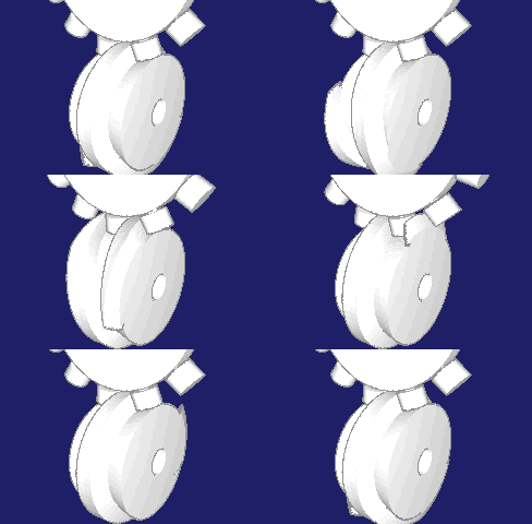
Track count = Step angle / Pitch angle
The animation shows on the left a one-track globoidal indexer, in the middle a double-track indexer and on the right a three-track indexer:
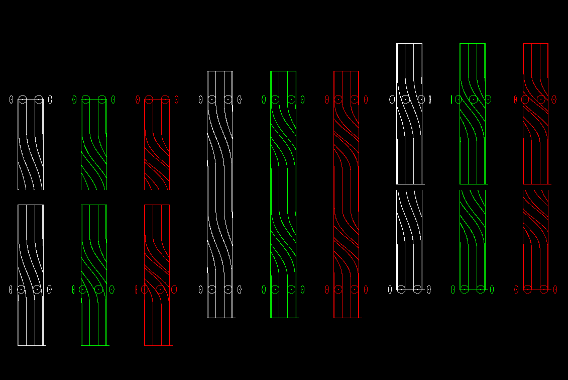
This can also be transferred to parallel cam gears.
If n (at least 4) rollers are involved in the motion transmission of a step, it is
Track count = n / Plane number - 1
Parallel cam gears create intersection points between the cam profiles that can be calculated for the individual rollers. The number of intersections m for a single cam is
m = Plane number • Track count
MS, MS30, MS50, P5, TR, MT
These are common names for the best-known laws of motion used in indexing cam gears:
MS = Modified Sine
MS30 = Modified Sine with 30% straight line insertion
MS50 = Modified Sine with 50% straight line insertion
P5 = 5th degree polynomial
MT = TR = Modified Trapezoidal
Every gear manufacturer can have its own naming system, and of course there are many more laws of motion.
Indexing cam gears
Indexing mechanisms based on
are particularly powerful and flexible and therefore very common.
We have therefore donated a separate page for each of these three gear types. Please click on the menu items!
Several well-known manufacturers of camd step gears worldwide rely on our software OPTIMUS MOTUS!
Servo controlled stepping movements
A possibility often used in practice to generate step movements or generally continuous movements are Servo drives.
Geneva drive / Maltese Cross
A classic among the indexing gears is the Maltese cross gear, in which the input and output shafts are parallel.
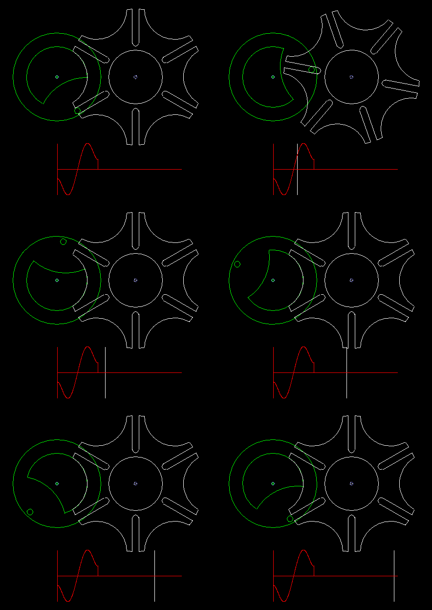
A circumferentially driven bolt engages in one of the grooves of the driven wheel and moves it by one pitch. Outside this indexing phase, if the bolt does not engage in a groove, a lock fixes the follower. If several bolts are mounted on the driving wheel, possibly even distributed unevenly, various indexing rhythms are conceivable.
Since the bolt must tangentially enter the straight grooves, the indexing angle results directly from the step angle, so can not design the indexing angle or the ratio of rest time to indexing time freely.
At a step angle of 90 degrees, which also results in a indexing angle of 90 degrees, the four grooves recall together with the circular recess on the output disk for locking to a cross of the Order of Malta. That's how the name comes about.
The classic Maltese cross gear is jerky, ie with uniform input drive you get acceleration jumps on the output shaft.
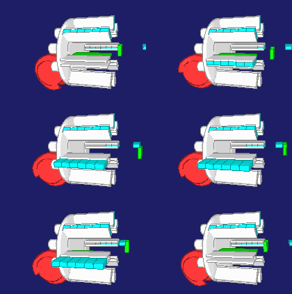
The animation shows a step of the Maltese cross, and below in red you see the acceleration cam at the transmission output. In addition to the jerk (= acceleration jump), the course of the acceleration is not optimal.
For higher dynamic requirements, the Maltese cross mechanism is therefore not suitable.
Because the output of a Maltese cross gear looks like a star, it is sometimes called "star wheel". A star wheel mechanism works but very different than a Maltese cross gear.
The Maltese cross gear can be modified with the aid of a cycloidal gearbox on the drive side so that a very harmonious motion sequence without jerk is created at the gearbox output. The second animation shows such a transmission including acceleration diagram. However, the maximum values of the acceleration are very high, considerably higher than the accelerations which one achieves with cam-type stepping gears.
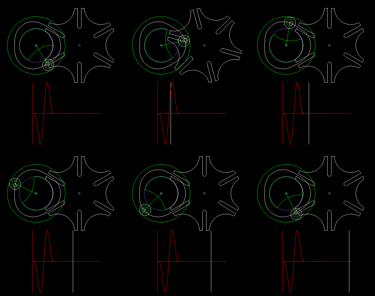
Instead of the cycloidal transmission, all mechanisms can be connected upstream, which introduce the pin on its coupling cam tangentially and with curvature 0 into the grooves on the follower. With four-bar linkages, however, there are no attractive solutions in terms of accelerations at the transmission output, and higher-coupled linkages make the kinematics very complex.
Star wheel mechanism
Star wheel mechanisms are indexing gears based on gears with constant transmission ratio. This base gear can be designed with spur or rack gears.
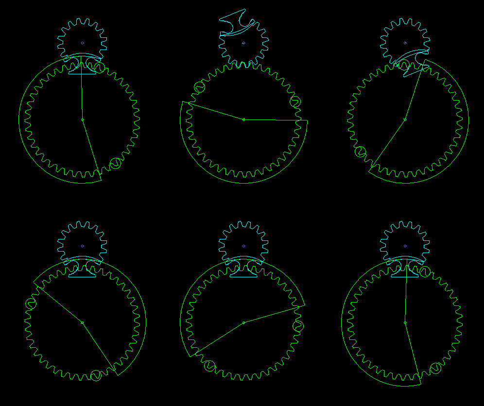
The idea is to stop the transmission by leaving out some teeth on the output gear. Cam segments ensure a relatively smooth transition between constant angular velocity in the middle part of the indexing phase and the dwells.
A lock ensures that the output gear is fixed during the dwell phase.
Input and output shafts are parallel to each other.
Compared to the Maltese Cross, step number, step angle and dwell angle can be varied significantly wider. In addition, the step angles in a period need not be the same. Since the indexing phase is mainly traversed at a constant speed and only a small drive angle for the transition from or to the dwell remains, very large angular accelerations will occur on the output gear.
The star wheel transmissions is more variable than the Maltese Cross, but also more complex and expensive.
Star wheel gears are sometimes mistaken for planetary gears.
Cam with revolving lever
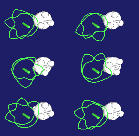
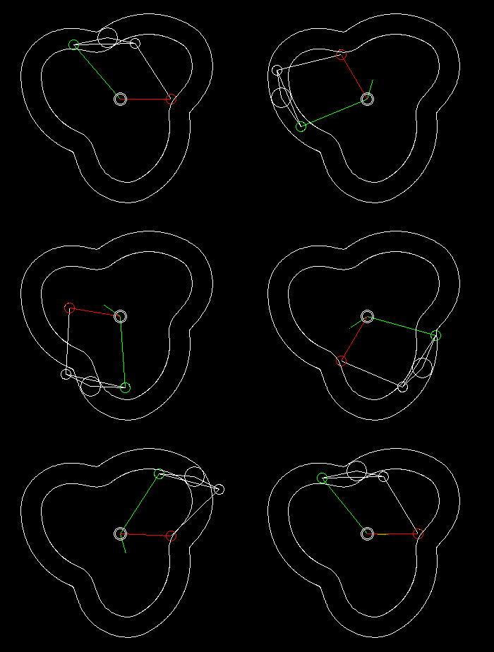
A simple type of cam-controlled step-action gearbox is presented in the following two animations.
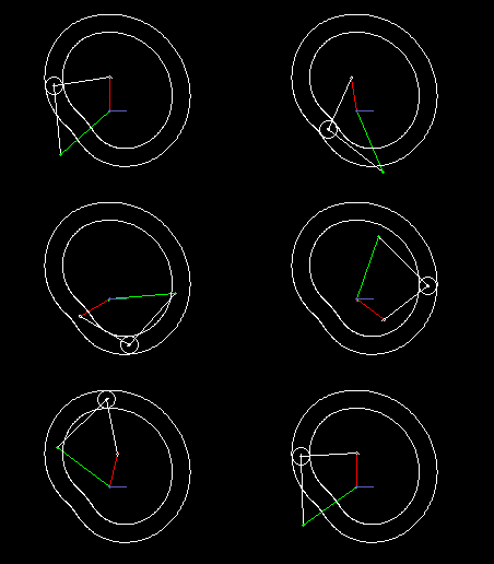
The first shows a single step, the second a triple step.
In green you see the uniformly rotating drive, in red the step-wise moving output. Via cam lever and linkage (both in white), the follower is delayed or accelerated relative to the drive so that short dwells arise at the transmission output.
Input and output shaft are parallel and close together, mostly even in on the same ayis. Although there is not as much freedom in motion design as in parallel cam indexing gears, cylindrical indexing cams or globoidal indexing cams, because you easily get mechanisms with very poor transmission angle, the transmission function can nevertheless be designed jerk-free.
Instead of a groove cam, ridge or double cams can also be used.
Wheels+linkage
Indexers with an approximate dwell can be implemented by combining a linkage with wheels.
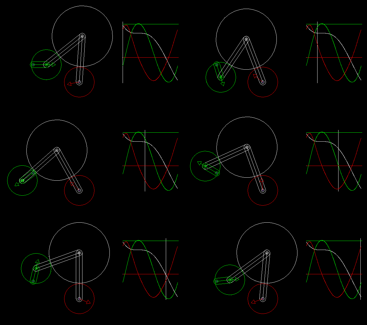
With the linkage synthesis functions of the OPTIMUS MOTUS software, we can numerically optimize the kinematic dimensions of linkage and wheels for the best possible compliance with the desired dwell angles.
The animation shows a linkage/wheels coupling and the progression of path (white), speed (green) and acceleration (red) of the rotation of the output shaft.
Longer phases of approximate dwell require more complex linkages. That makes the layout unattractive.
To the homepage of Nolte NC-Kurventechnik GmbH
Start Mechanisms Kinematics CamDesign Servo+PLC MotionDesign Training Software Service CamCalculation Imprint PrivacyPolicy
Terms IndexingCamGears Globoidal Cylindrical Parallel Geneva MalteseCross TrackCamIndexing Wheel+Linkage
11/06/21
• Software OPTIMUS MOTUS ® /
DasNolte ®
• All types of Cam Calculations
• Performance Optimizations
• Trainings and consulting
• App and Software Development
• PLC Motion Software
Cams, Mechanisms, Motion Design. Faster Machines. Since 1965.
