Energetic optimization of mechanisms
Saving energy, reducing CO2 emissions and protecting our common living space is one of man's most important goals. Of course, this also applies to mechanical engineering.
Energy is lost wherever it is transported, namely in the form of friction. No machine component has an efficiency of 100%.
If you're walking up to the fifteenth floor in a skyscraper and then back to the ground floor, your body will end up at the same height as it did at the beginning, so it has the same potential energy as before. Apparently, no energy has been lost. If only you would not sweat like that ...
A machine "sweats", too. The supplied power heats the cable, inverter and the motor, and the heat is dissipated into the environment. The motors drive gears, spindles, belts, chains, wheels, springs, levers and products. Under load parts deform rhythmically, are kneaded downright, because nothing is absolutely rigid, and thus produce waste heat. Air and oil are swirled and provide further heat losses. The machine is getting warm.
Now our very simple idea:
The less energy is transferred to the output, where the mechanics act on the product, the less energy has to be transported from the socket to the tool or the processed product and back again.
We optimize motion control so that as little energy as possible is transported!
Incidentally, this not only saves energy. It also makes machines faster, because mechanical energy transport with changing loads is accompanied by deformations and thus also by vibrations. Optimizing the energy flow also improves the performance and ultimately the cycle time.
Energetic optimizations are performed especially for very fast running machines, because of the performance and the freedom from vibration.
That's one of our favorite topics, and we would like to support you!
Skip to ...
- Energy diagram
- Drive torque
- Power balance
- Low energy turnover
- Energy-efficient movement design
- Reduced moment of inertia
- Torque compensation
- Torque compensation cams
- Compensators with springs
- Compensators with inertia
- Natural motion
- Flywheel
- Mass force compensation, frame force compensation
- Engineering design annotations
- Software
- Calculation
- Training
Energy diagram
The energy diagram in OPTIMUS MOTUS shows courses of kinetic and potential energies and of performance in the overall mechanism.
It serves to evaluate the energy flow in the mechanism and to derive measures to keep the total energy in the mechanism as constant as possible.
The reason: the more constant the energy in the mechanism, the less power the drive has to implement, and the smaller is the drive torque at the camshaft.
Drive torque
For cam gears and servo drives, the drive torque is of particular importance.
The maximum torque must be less than the maximum allowable torque in the powertrain, which is typically given by the motor or transmission, but sometimes by other components. The permissible maximum torque usually depends on the speed of the drive.
To avoid motor overheating, the effective value of the torque course, the "effective torque", must be smaller than the rated motor torque. Air or water cooling significantly increases the permissible permanent torque (rated torque) of the motor (order of magnitude: 30%).
If several components are driven by one motor, then the summed torque should be considered and optimized, ie the superimposition of all individual torque courses.
The interaction of return springs on spring-loaded cams can sometimes be optimized so that the energy in the overall mechanism is kept approximately constant. For this purpose, the working directions and the parameters of all return springs are optimized in a common consideration. This finally drops the drive torque on the camshaft significantly.
Harmoniously designed cumulative torque courses on a camshaft with low extreme values avoid vibrations in the drive train.
You should be careful when a camshaft is driven by a chain. When a sprocket has only few teeth, vibrations can be excited by the polygon effect.
Especially in the case of longer chains, their elasticity must be taken into account, to avoid torsional oscillations on the camshaft due to alternating loads.
Particularly interesting is the deceleration simulation offered by our software OPTIMUS MOTUS to investigate the emergency stop behavior of a cam control. For a kinetostatic simulation model you obtain precise information which braking torque is needed to brake the camshaft to a standstill within a defined time from any intermediate position. It is just as easy to determine how long it will take to stop the camshaft with a given braking torque.
Back to top
The power balance is a simple approach to determine the required drive torque for a mechanism. It is applicable to a mechanism with a single continuous drive with the drive function psi(phi). The drive serves as an energy source and as a surplus of excess energy. phi is a time parameter, eg the time t in seconds or a smoothly running clock angle from 0 to 360 degrees.
The energy stored in a mechanism is usually not constant over the motion cycle. The mechanism stores energy in the moving masses as potential and kinetic energy. Springs store potential energy. In addition, energy for processing can be passed on to the products or in the form of friction to the environment. The energy stored in the masses changes with their vertical position and their speed. The energy stored in the springs varies with the spring length.
The trick now is that the power balance does not depend on which path the energy takes in the mechanism, ie how the mechanism is structured in detail. The mechanism can be considered a black box. You just have to know the movements of the energy stores and the driving motion in order to calculate a drive torque.
In many practical applications, essentially one large mass moves at the output of the mechanism according to a defined motion diagram, and the drive function is also known. This does not have to be a linear function with constant speed. The drive should not come to a standstill so that omega does not become 0 (see below).
First, you calculate the total energy W(phi) in the mechanism over the time angle phi.
By derivation after the time you get the course of the power P(phi), which is implemented by the mechanism and thus must be implemented by the drive:
P(phi) = dW(phi) / dt
The drive power Pan(phi) is represented as
Pan(phi) = Man(phi) • omega(phi)
It is
omega(phi) = d(psi(phi)) / dt
With the equation P(phi) = Pan(phi) the drive torque Man(phi) can be calculated:
Man(phi) = P(phi) / omega(phi)
P = power in W
Man = drive torque at the motor in Nm
Pan = drive power in W
psi = drive angle in rad
omega = drive angular velocity in rad/s
At constant cam speed, P ~ M resp. M = P / omega = P / (pi•n/30) with n = speed in rpm.
Low energy turnover
In order to save energy, servo drive technicians propose to feed back the braking energy of servo drives into the converters to reduce energy losses. That's a good point, but unfortunately the energy yield through feedback is not very large.
In our opinion it would be wise, to design the mechanics itself for power balance so that the drive has to transfer only little energy. Where no braking energy accumulates, you do not have to worry about brake heat or feedback!
Energy-efficient motion design
Motion design is a very cost effective (cheap) way to save energy in mechanisms.
For cams and servo drives, the movements can be designed so that as little energy as possible is exchanged between the drive and the mechanics.
For example, by ...
- Selection of motion laws with low dynamic momentum value Cmdyn. The smaller the characteristic value, the lower the energy conversion. The well-known 5th order polynomial has a characteristic of Cmdyn = 6.69. The also common modified sine is characterized by Cmdyn = 5.46. The energy-saving polynomials developed by us, on the other hand, have characteristics of Cmdyn = 3.58 (jerk-free) and Cmdyn = 2.70 (jerky).
- Collision optimization, which minimizes the overall dynamic load, and therefore automatically also the energy turnover.
- Favorable overlay of performance requirements. The overall motion sequence can be optimized to this effect, for example by temporally shifting start and end points and by selecting laws of motion that compensate for power output and power take-back on a drive as best as possible. When optimizing the motion, it is always necessary to consider the torque sum or the total power.
Reduced mass moment of inertia
In mechanisms, the ("reduced") moment of inertia related to the drive shaft is usually not constant, but varies with the gear ratio between drive and mass motion.
It is very important to take this into account when designing the drives, otherwise you will simply receive incorrect results. If the results are wrong, you select drives that are too large (expensive!) or too small (problems with commissioning, discussions with the customer, even more expensive!).
A simple and very common example of large non-linearity is the slider-crank, which is very popular because of the toggle effect (large forces in the end positions) and the mechanically accurate compliance with the movement end positions.
In general, the reduced moment of inertia Jred(phi) at the mechanism drive, which is to replace all inertial masses, can be determined by the following relations:
Thus, the drive torque Mkin due to carrier masses:
In many high-speed mechanisms, the drive torque due to inertial masses outweighs so clearly that one can neglect other influences in the optimization.
Example: Slider-crank mechanism

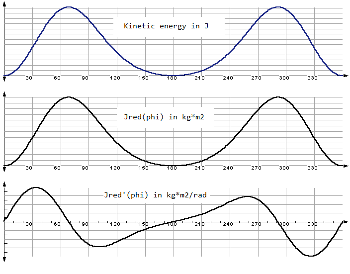
The curves of the kinetic energy Wkin, the reduced mass moment of inertia Jred and the derivative J’red :
Power compensation / torque compensation
The power compensation keeps the drive power - and at constant drive speed also the drive torque - of a mechanism as constant as possible. Without friction and power needed to process articles, the drive torque of a mechanism could be mathematically reduced to zero (!).
Goals:
- Save drive energy
- Reduce power peaks
- Reduce moment peaks
- Improve uniformity
- Reduce excitation of drive shaft vibrations
Mechanisms with a constant, small drive torque are very easy to control, consume little energy and can run more smoothly.
At constant drive speed, power compensation is synonymous with drive torque compensation.
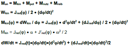
Jred is a reduced (notional) mass moment of inertia and stores the same kinetic energy at the drive speed dphi / dt as all actual mechanism parts.
The most common power-balancing measures:
- Flywheel: low design effort, lower fluctuations in drive torque and speed, higher kinetic drive energy, acceleration and braking, longer start-up and braking times
- Change of mass parameters (manually by trial or by numerical optimization)
- Matching the drive motion profile to the natural motion
- Adjusting the output movement to the load cam (optimize laws of motion)
- Spring compensators
- Torque compensation cams with compensation spring
- Inertial compensators
- Torque compensation cams with balancing mass
- Additional mechanisms or servo drives
Depending on which power-sharing measures are used, you get
- Complete power compensation
- Complete power compensation at a certain operating speed
- Partial power compensation (reduction of torque fluctuation) at all speeds
- Partial power compensation at operating speed
Torque compensation with cams
If the torque feedback of the mechanism is too high, it can be partially or fully compensated with a torque or power compensation cam. The torque compensation cam should be placed as close to the working mechanisms as possible.
The torque compensation cam produces exactly the torque feedback that the working mechanism demands from the drive. When the mechanism returns energy to the drive, the balancing mechanism picks it up directly. When the load-balancing mechanism is close to the working mechanisms, the overall set of work and balancing mechanisms no longer exert a retroactive torque on the drive.
The contour of the moment compensation cam is calculated from the cumulative torque profile of all working cams.
In principle, all cam coupling gears can be used as torque compensation cams. However, energy stores (springs, masses) must always be included in the mechanism. These energy stores act as a source and sink for the dynamic performance requirements (= moment requirements) of the work mechanisms.
Note:
Torques due to friction or payloads can not be fully compensated because the energy that is released into the process or released as heat can not be fed back into the drive. By means of a torque compensation cam, however, the irregular energy requirements of the process or the uneven demands on frictional energy can be distributed uniformly over the entire movement cycle, so that a constant residual torque occurs at the drive.
Note:
For complete torque compensation across all speeds at least two compensation cams are required:
One cam with a compensating spring. This compensates all drive torques due to static loads (springs, process forces, weight).
One more cam with a balancing mass. This compensates for all dynamic drive torques that arise due to inertial mass. If necessary, this cam can be replaced by a pressure control on the balance cam for the static loads.
The reason for this is that the retroactive torques due to static loads and inertia depend differently on the speed:
- Static loads are independent of the drive speed.
- Inertia loads increase proportionally to the square of the speed.
Often it is sufficient to compensate for the drive torque at a certain operating speed. In this case, a single compensation cam with compensating spring is sufficient.
Frequently used cam gear types for a torque compensation mechanism:
- Cam with rocker arm and compensating spring (see picture) (complete compensation only possible for one speed)
- Cam with rocker arm and pressure cylinder (complete compensation for all speeds with speed-dependent pressure control possible)
- Cam with plunger and compensating spring (complete compensation only possible for one speed)
- Cam with plunger and pressure cylinder (complete compensation for all speeds with speed-dependent pressure control possible)
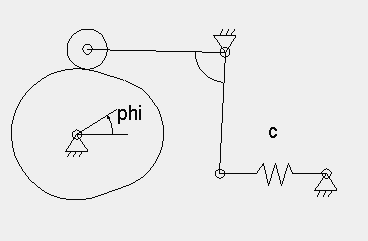
The greater the stiffness of the compensation spring, the smaller the stroke on the compensation cam.
Due to the compensation cam, the total torque (sum of drive torque of the working cams and the compensation cams) becomes zero:
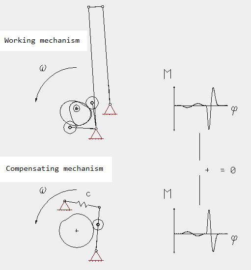
We would like to calculate torque compensation cams for you. Contact us! Wouldn't a mechanism with drive torque 0 (or just friction) sound nice?
Spring compensators
Assuming that you have an arbitrary mechanism with a drive torque course M an (phi), and you want to compensate this drive torque with the help of a spring as an energy buffer, then the course of the spring length over the drive angle can be calculated.
It does not matter how the mechanism works which requires the working torque M an (phi), and no matter how the torque compensation mechanism is built up!
Advantages of spring compensators:
- Complete compensation of the potential energy at all speeds possible
- Complete compensation of the kinetic energy at an operating speed possible
- Partial compensation often possible with little effort
Disadvantages of spring compensators:
- Risk of natural vibration of the balancing springs
- Compensation of inertial loads only possible for one nominal speed
Inertial compensators
In a uniformly driven mechanism, the torque due to inertial masses can be compensated by coupling an additional balancing mechanism to the drive shaft which moves an additional mass moment of inertia with the function psi (phi):
Advantages of inertial compensators:
- Complete compensation of the kinetic energy for any constant driving speed possible
Disadvantages of inertial compensators:
- High design effort and increased space requirements
- Increased frame and joint forces
Natural motion
The natural motion arises for a mechanism when you disengage the drive suddenly. The drive runs without driving torque then. In general, the natural motion is accelerated, not steady.
If you now operate the mechanism actively with a driving motion that corresponds to the natural motion, the drive needs to apply permanently no torque, except to overcome friction and useful forces.
The required non-uniform driving motion can be initiated exactly by indexing cams, non-circular gears, servo drives or approximately by linkages.
At approximately constant potential energy:
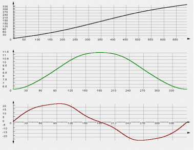
Slider-crank example:
Drive torque with steady input motion on the crank (left) and accelerated moving mass on the slide (pivot point right):

Drive function for crank drive torque Man = 0, that is, when the crank is moved this way by means of a servo drive, a pair of non-circular gears, an indexing gear or approximately a linkage, only the friction torque must be applied:
Flywheel
Flywheels are used in mechanical transmissions with constant drive speed to keep the fluctuations of the drive angular velocity and thus the current motor drive torque small. They are only found in exceptional cases today.
In connection with controlled drives (servo drives), they usually make no sense.
With negligible fluctuation of the reduced mass moment of inertia, the flywheel can be designed for the useful and friction moments:
W* = work of process loads and friction for a cycle of motion
Advantages of the flywheel:
- Low design effort
- Lower fluctuations of drive torque and speed
Disadvantages of the flywheel:
- Higher kinetic drive energy, so higher acceleration and braking work
- Longer start-up and braking times
Dynamic force compensation, frame force compensation
Machines tend to vibrate at higher speeds in their lineup. They almost shake each other. The same applies to elastically suspended assemblies in a fixed frame, eg heavy cantilevered components. These are natural oscillations caused by the combination of large, high-accelerated masses and a light, elastic frame construction.
In the past, more than 40 years ago, machines were sometimes paid by weight. The heavier the machine, the higher the price. The frame - and all the other parts - were often made very massive. The vibration excitation in the frame is stifled in the bud. This time is over, today one builds lighter, with less material, and thus more elastic and potentially vibration-prone. If masses are accelerated, the frame reacts rather with twisting.
Unfortunately, the moving masses can not be arbitrarily reduced, and the number of cycles should generally continue to rise. Although the stimulation of the frame by mass forces can be reduced by movement design, but sometimes the residual stimulation remains so great that further action is required.
Then you try to compensate for the excitation of the frame by forces and tilting moments with the help of balancing weights. These balancing weights are applied either in the form of additional masses or recesses on the existing mechanism parts, or additional cam or coupling mechanisms are introduced to compensate for the frame excitation of the working mechanisms exactly or approximately. We call this "mass balance" or "frame force compensation".
In principle, this is often quite simple:
For each working mechanism, you make a copy rotated by 180 degrees and offset in such a way that the centers of gravity run on the same line of action - done. If a mass m in the working mechanism moves in, let's say, +X, then the balancing mass automatically moves in the same way in -X. Both masses then balance each other in their effect, and there are no tilting moments.
The problem is that this approach requires a lot of space, often where it is not available, and that, of course, it is very expensive.
But you can simplify this by trying to attach countermeasures directly to the moving parts of the working mechanism.
The real art is to achieve a sufficiently effective frame force balance with simple and inexpensive measures.
We would like to support you with our experience and our software OPTIMUS MOTUS.
For the frame force compensation, we use special numerical optimization algorithms.
Of course, the balancing masses also require energy and increase the required drive torque. If the drive torque should be too large due to the balancing weights, a drive torque compensation can be performed in addition, in such a way that no additional dynamic frame forces arise.
With a combination of mass balance and torque compensation, one can achieve a theoretically perfectly balanced mechanism that does not introduce dynamic forces and tilting moments into the machine setup and that requires only a small constant drive torque to apply the friction effort.
Almost a perpetuum mobile!
Engineering design annotations
In practice, the following general tips have proven useful for designing energy-saving motion controls:
- Mechanics prior to electrics prior to pneumatics
- Demand not more motion constraints than necessary
- Only demand what is technologically necessary, allow large tolerance ranges
- Move what is lighter: workpiece or tool
- Arrange return springs so that they balance each other's energy flows and energy flows optimally
- Modifying eigenmodes so that the work of different excitation forces mutually reduces or abolishes each other
- Shrink masses at places where high speeds occur
- Avoid dampers
- Do not fully utilize drive speed ranges, often about 1/3 of the maximum is optimal
To the homepage of Nolte NC-Kurventechnik GmbH
Start Mechanisms Kinematics CamDesign Indexing MotionDesign Training Software Service CamCalculation Imprint PrivacyPolicy
EnergyDiagram Torque Power EnergySavingMotion Inertia PowerBalancing EigenMotion Flywheel FrameForceBalancing Hacks
11/06/21
• Software OPTIMUS MOTUS ® /
DasNolte ®
• All types of Cam Calculations
• Performance Optimizations
• Trainings and consulting
• App and Software Development
• PLC Motion Software
Cams, Mechanisms, Motion Design. Faster Machines. Since 1965.
