Kinematics
Kinematics is the description of movements on a purely geometric basis with location, speed and acceleration over time. It is a branch of mechanics.
For the development of machines, the consideration (and control) of their kinematics is essential, especially when cams, linkages or servo drives are involved. Movements take place in machines, and they have to be coordinated in such a way that the mechanics as a whole perform a meaningful function and the parts do not collide with each other.
The following figure shows a 2D transport rake of a packaging machine. A special four-bar linkage generates a "bread-shaped" coupling cam with an approximate straight-line guide. An additional dyad holds the rake exactly horizontal at all times.
Kinematics is the starting point for further dynamic considerations in order to determine the loads and power flow due to masses, springs, friction, etc. From the acceleration of a center of gravity, for example, the inertial force can be determined on the moving part and thus the drive torque on the servo motor. From the rate of change in length of a spring is calculated which power the spring converts.
As "kinematics" colloquially also the mechanism (the kinematic chain) is called, with which a movement is implemented.
The simulation and optimization of the kinematics of mechanisms has been the basis of our work for 45 years and also of the kinematics software OPTIMUS MOTUS, supplemented by dynamic considerations (kinetics and vibrations).
Animation
Animations clearly show where kinematics and motion diagrams can be further improved.
As early as 1984, before the advent of "kinematics modules" in CAD systems, we graphically displayed the calculated gear positions in rapid succession on the computer screen, thus creating animations and performing motion simulations. We have developed special programs to make the movies on the screen flicker-free and fast enough. If the animations are "flashing" or too slow, you can hardly see the actual movement.
Animations have always been a very important means of communication for us. When we discuss issues or solutions to cams and joint gears with customers and the kinematics is not trivial, we always use animations as a basis for discussion.
For the comfortable, flicker-free and fast presentation of motion simulations, our customers can now use the winfilm program developed by us free of charge.
For our purposes, it is much better suited than media players designed for videos. In addition, animations for winfilm are usually orders of magnitude more compact than AVI files. winfilm exports but on request also AVI files.
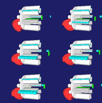
The image above with the six-bar mechanism shows the menu items of winfilm. The mouse can also be used to zoom in and out.
The kinematics provides well-known and important evaluation parameters for cam and coupling gears:
- speed
- acceleration
- jerk function
- transmission angle
- radius of curvature
Although machines and mechanisms are always spatial (3D), most practical mechanisms can be handled very well in 2D. In 3D kinematics, each part has six degrees of freedom (displacement in X, Y, Z and rotation around X, Y, Z), in a 2D kinematics only three (displacement in X, Y and rotation around Z). In 2D, software and users only have to deal with half the complexity. In 2D, you can sketch and model faster and easier. And the practice shows that the software users like to take advantage of this fact, even if 3D looks cool in the first instance.
Our kinematics and dynamics software OPTIMUS MOTUS supports 2D and 3D kinematics and motion simulations.
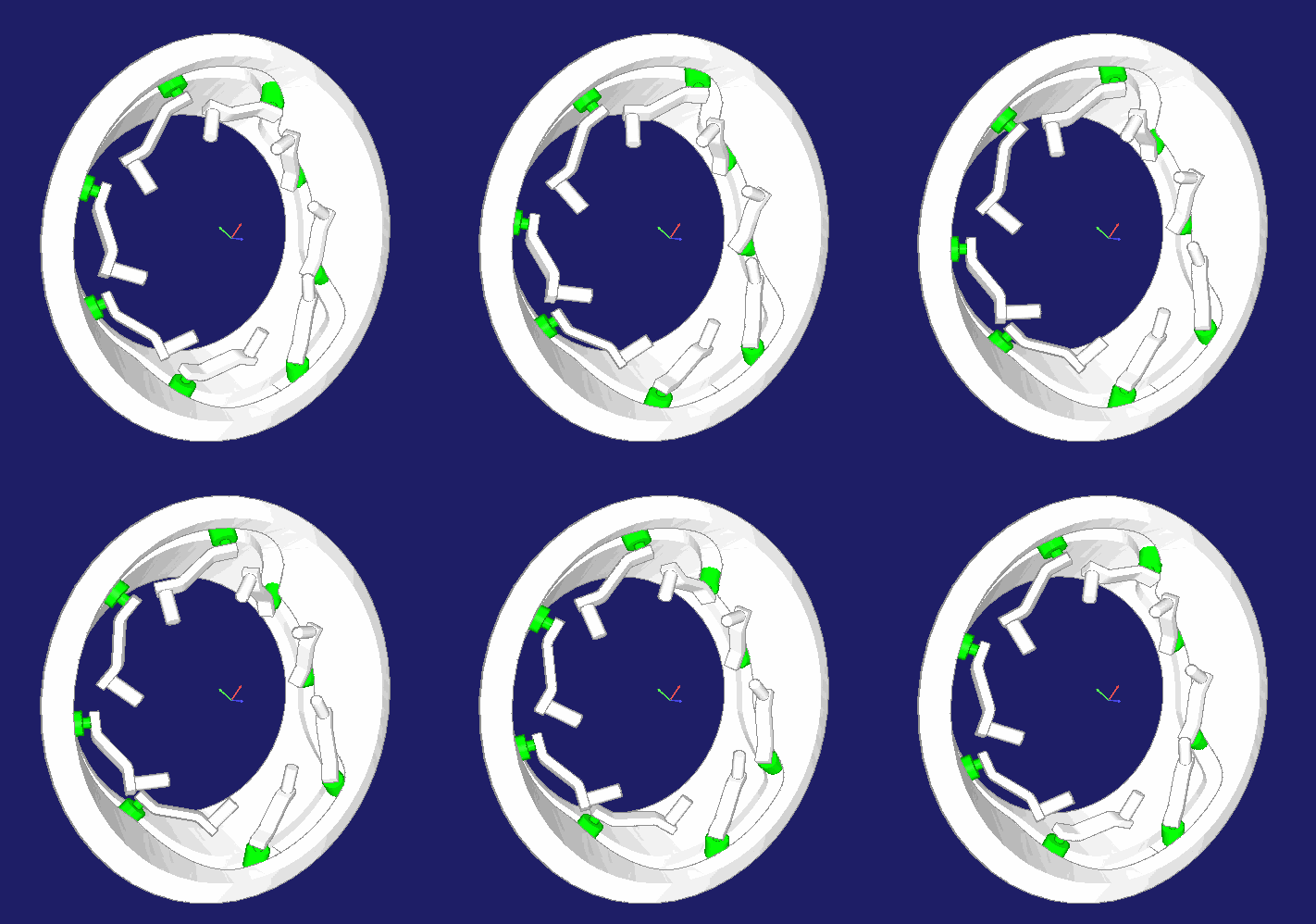
Here is an animation from OPTIMUS MOTUS for a spatial cone cam with rotating, spatially pivoting levers from a machine for the production of cable windings:

Based on the kinematics (movements purely geometrical), mechanisms are also examined with regard to their dynamics, ie the loads occurring during the movement (forces, moments, pressure, stresses in the material, deformations).
We distinguish between the following model classes:
- Kinetostatics (rigid bodies, no elasticities, quasi-static view)
- Kinetoelasticity or elastokinetics (with component deformation due to external forces, but no natural vibrations)
- Kinetics or dynamics (with component deformations including natural vibrations)
Kinematic analysis
In kinematic "analysis", the position of all moving parts of a given kinematics is determined on the basis of motion specifications. In principle, movements can be specified at all points of the kinematic structure, not only where the drive is finally mounted.
There are different approaches to kinematic analysis:
- Formula derivation based on sketches
- Dyads
- Numerics
In the past, we have used all three approaches, but today we prefer a special numerical method, because mechanisms can be modeled very easily and conveniently this way. Each moving part has degrees of freedom (independent movement possibilities), 3 in a plane and 6 in 3D. With constraints (equations), for example in the form of joints or motion diagrams, the dimensions of movement are restricted. Linkage positions can be calculated only if there are the same number of constraints and degrees of freedom. Our software OPTIMUS MOTUS organizes this calculation by itself, without the user having to intervene. Various optimizations of the method ensure that the calculation runs very fast.
Kinematic synthesis
The kinematic synthesis is the reverse of the analysis. You specify a movement or a movement behavior and then look for a mechanism that performs this best possible.
Examples:
- Fittings ("hinges") for furniture, windows and doors
- Boot flaps, machine guards (should not fall down at the top and close securely at the bottom)
- Steering rods of vehicles
- Mechanical presses
In the first step, the structure synthesis, one chooses a suitable kinematic structure. The kinematic structure is the way the mechanism parts are connected by joints.
In the second step, the appropriate kinematic dimensions are determined with analytical or numerical methods.
Kinematic synthesis is THE task of the transmission theory par excellence.
We generally use parametric mechanism models and a system of numerical synthesis methods for the synthesis, because this way we are completely free in the specification of the objective function, that is, whereupon we want to optimize the kinematics at all.
Learn more on the page "Linkage Synthesis"!
To the homepage of Nolte NC-Kurventechnik GmbH
Start Mechanisms CamDesign Indexing Servo+PLC MotionDesign Training Software Service CamCalculation Imprint PrivacyPolicy
11/06/21
• Software OPTIMUS MOTUS ® /
DasNolte ®
• All types of Cam Calculations
• Performance Optimizations
• Trainings and consulting
• App and Software Development
• PLC Motion Software
Cams, Mechanisms, Motion Design. Faster Machines. Since 1965.
