Linkage synthesis
Over 100 years after Burmester, the synthesis of coupling gears (linkages) is still a tricky field for mechanics technicians.
The goal in linkage synthesis is always to find a mechanism with desired guiding properties, transfer characteristics or energetic properties.
For example, it should generate a specific coupler curve or a predetermined transfer function..
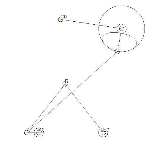
The image shows a six-bar coupling gear, which holds a relatively long and accurate fixed position on the output rocker C0-C when you turn the crank A0-A by 360 degrees. Here the transmission function of the linkage:

The synthesis task becomes easier if you allow the use of cam joints, because then you can usually relatively quickly determine a suitable transmission structure and calculate the curves directly with which the mechanism has the given properties.
Linkage synthesis is for us the more specific task of finding mechanisms only with revolute and sliding joints in order to implement the motion task.
However, the search for mechanisms with wheels and traction devices belongs to the same category of tasks because the solution methods are similar.
The essential point is to do without freely definable cams.
This makes linkage synthesis so difficult, because then you have only a finite number of parameters to optimize the transfer function, the coupler curves, the drive torques and the joint forces. As a rule, the specifications can only be achieved approximately. You seek the mechanism that fits best to the demands, and hope that the deviations from the specification are still acceptable.
But this effort can be worthwhile:
Mechanisms that include only revolute joints are particularly easy to manufacture, inherently low-wear and harmonious in their movements.
If you want to achieve very high speeds or reduce wear, you should try to find mechanisms only with revolute joints that meet the specified motion task with a defined tolerance.
Often it is quite possible to replace cams or sliders with solutions with revolute joints!
With our services and our software OPTIMUS MOTUS we favor a numerical approach with which we can in principle find solutions for any linkage synthesis task. We not only consider kinematic specifications, but also kinetostatic and energetic ones.
Skip to ...
- Structural synthesis
- Drawing-based dimensional synthesis
- Numerical dimensional synthesis
- Newton's method
- Define suitable optimization parameters
- Target function
- Parameter influence calculation
- Search field calculation
- Search optimization step
- Composite optimizations
- Example straight-line generating mechanism
- Software
- Calculation
To the homepage of Nolte NC-Kurventechnik GmbH
Structural synthesis
The synthesis of a mechanism for a motion task begins with finding a suitable transmission structure and defining it for the subsequent dimensional synthesis. Typical movement tasks are to transform motions, guide points on a part or guide planes.
- Simpler mechanism structures are better than complex ones.
- Few moving parts are better than many moving parts.
- Revolute joints are better than linear joints or cam joints.
The first candidate for many synthetic tasks is in most cases the four-bar linkage. The dwell-generating 6-bar linkage in the first image contains a four-bar linkage with specific curvature properties on the coupler curve. Correspondingly, the dyad C0-C-K was then constructed in accordance with these curvature ratios.
If cam gears or servo drives with electronic curves are allowed, you have a very good chance of fulfilling the motion task exactly, but with a correspondingly complex mechanism structure.
Then you require as many cam gears as the motion specification has dimensions. In the synthesis of a transfer function or a coupler curve, for example, a single cam gear is needed. In a point guide with specification of point speed over time, or in a plane guide two cam gears are required, in a plane guide with specification of speed over time even three.
Mechanism structures can be found in many different sources, for example:
- Solution catalog in OPTIMUS MOTUS
- Kinematic textbooks
- VDI guidelines, eg 2727
- DMG-Lib
- Patent researches
- Own drawing archive
- Experience of older engineers
- Company or association-specific solution collections
- Model collections of universities
- Everyday items (open your eyes, many things have already been invented, just for other purposes)
- Brainstorming
Drawing-based dimensional synthesis
Numerous older textbooks for coupling-gear theory describe numerous drawing-based methods to find the kinematic dimensions of mechanisms for very specific tasks. These procedures are used with compass and ruler. Today, however, it will be more likely to fall back on the CAD system or an interactive geometry software. The same methods can be found in many different sources, including the internet, and are described there in different ways.
Example:
2 end positions of the output of a rocker arm at predetermined frame points
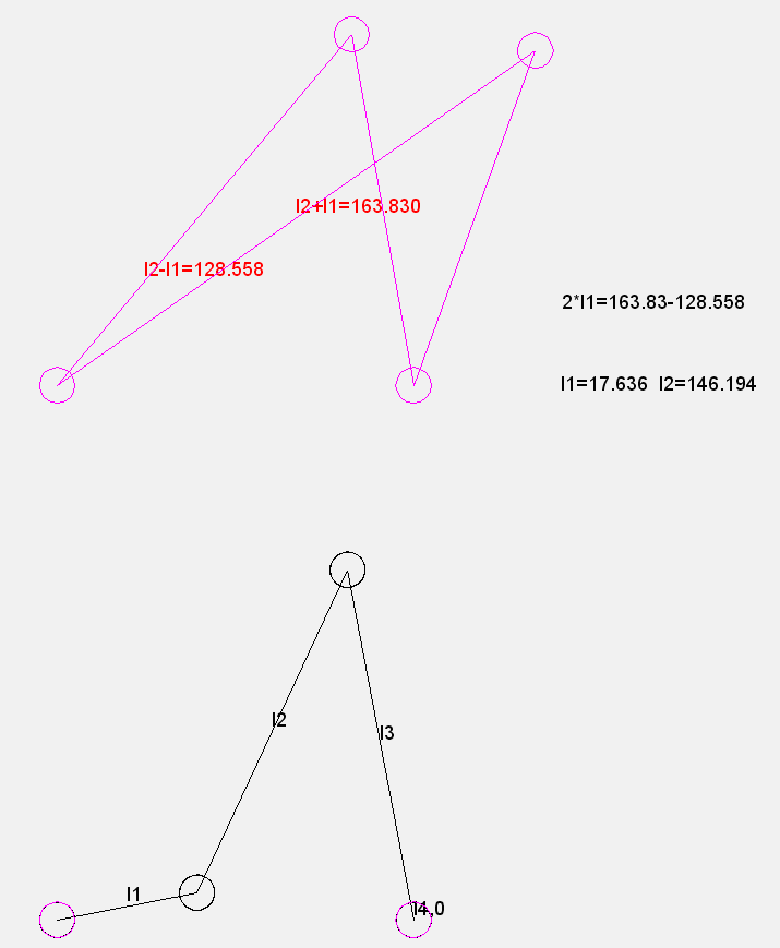
Example:
Find a four-bar mechanism with revolute joints, in which the coupler passes through three defined positions in the plane.
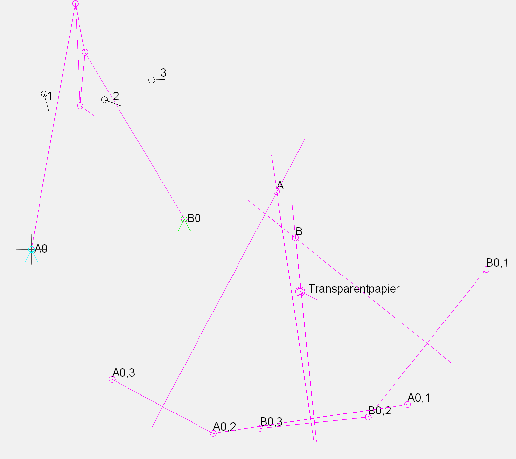
Method:
1. Select frame points A0 and B0
2. Specify coupler plane positions 1, 2 and 3
3. Place "transparent paper" in coupler plane positions 1, 2 and 3 and transfer A0 and B0 respectively
4. Draw circles around the transferred A0 or B0 points, circle radii = bar lengths, circle centers = A or B respectively
From today's point of view, however, the classical methods of graphic synthesis raise some problems:
Problem 1: There are a lot of different procedures for each well-defined prerequisites, and it is extremely hard (thus expensive) to learn and master all of these procedures.
Problem 2: The methods and the explanations of the method are difficult to understand without special linkage theory training.
Problem 3: Special additional technological requirements (forces, collision avoidance) can generally not be taken into account.
We think that it is much more attractive to have a single, relatively simple methodology to solve all of the tasks!
Numerical dimensional synthesis
The idea of using a single methodology for all types of mechanism synthesis leads us to numerical dimensional synthesis.
With this method we optimize kinematic dimensions of a mechanism structure, but also motion specifications, mass distributions, spring parameters and values for any other parameters in order to meet the technological requirements in the best possible way.
The sum of the technological requirements is summarized in one or more target functions.
The target function is itself subject to optimization.
Procedure (for all tasks the same!):
1. Select mechanism structure
2. Set variable parameters
3. Define target functions
4. Determine the influence of the parameters on the target functions in different linkage positions
5. Select parameters to be optimized
6. Decrease number of optimization parameters (recognize and formulate parameter dependencies)
7. Perform search field calculations
8. Optimize the best solutions found in the search field, using Newton's or Search Step methods
9. Possibly improve target function and walk through the process again
The number of parameters to be optimized should be kept as low as possible, since the complexity of the synthesis task increases exponentially with the number of parameters.
This unified numerical methodology is much more powerful and much easier to understand than the variety of graphical synthesis methods.
We would like to assist you with this method in finding optimal mechanisms!
Newton's method
The Newton method searches X for the equation f(X) = 0.
f is usually an objective function, X is the vector of the optimization parameter values.
The Newton method is suitable for numerically stable, relatively simple optimization tasks and converges very fast. It requires the definition of N independent target functions when there are N optimization parameters. It is applicable when there is certainly an exact solution to the synthesis task near the starting point.
Application examples:
- Determination a coupling rod length for a maximum cam radius
- Determination of a crank radius and a coupling rod length in the four-bar linkage for a given rocker angle range psimin .. psimax on the output bar
- Solving non-linear equations as part of the optimization parameter number reduction (means for resolving parameter dependencies)
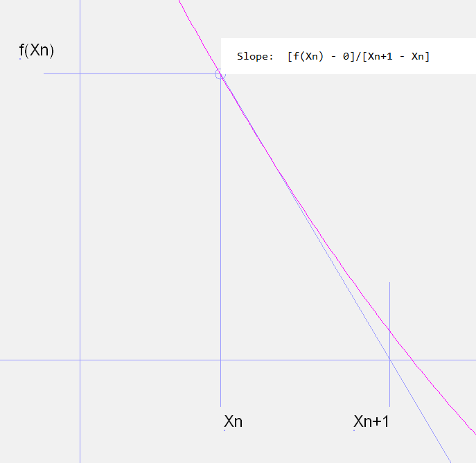
Algorithm for one dimension:
Given: start value X0
Step: Xn+1 = Xn – f(Xn) / f'(Xn)
Algorithm multidimensional:
Given: start vector X0
Step: Xn+1 = Xn – inv(A) • F(Xn)
F is the N-dimensional objective function vector.
X is also N-dimensional.
A is the Jacobian matrix dfi / dxj
inv(A) is the matrix inverse to A
As a rule, the Newton method achieves high accuracy with just a few steps. The iteration can then be replaced by a fixed calculation sequence with a constant number of iteration steps:
Start value X0
X1 = X0 - f (X0) / f '(X0)
X2 = X1 - f (X1) / f '(X1)
X3 = X2 - f (X2) / f '(X2)
The differential quotient can be used to calculate the derivatives
f '(X) = [f(X + h) - f(X)] / h
with the variation increment h. This way you do not need to derive f'(X) analytically, but only the equation f(X) = 0 itself to be solved:
Start value X0
X1 = X0 – f(X0) / [f(X0 + h) – f(X0)] • h
X2 = X1 – f(X1) / [f(X1 + h) – f(X1)] • h
X3 = X2 – f(X2) / [f(X2 + h) – f(X2)] • h
Optimization parameters
To describe the kinematics of a mechanism many parameters are often needed. Most of these are ultimately dependent on a few format parameters.
For the numerical optimization of kinematic dimensions ...
... as few parameters as possible are used. The complexity of optimizations increases exponentially with the number of optimization parameters. With 4 parameters the computation time can already become so great that a systematic search field computation is no longer feasible.
... only independent parameters are used. Example: If the sum a + b is to be optimized to 0, and if a and b are the optimization parameters, b = -a is always the optimal solution, independent of a.
... parameters are used that have a approximately linear influence on the target function. The target functions should change as evenly as possible with the optimization parameters.
Target function
A target function is a clear evaluation of a specific mechanism candidate, which is calculated in the synthesis process.
In the Newton method, the target function corresponds to an equation in the equation system whose solution you look for. There are as many target functions as optimization parameters in this method.
Search field calculation or search step optimization uses only one scalar target function, which depends on all optimization parameters. The target function then calculates a single number to evaluate the mechanism candidate. The optimizers look for mechanisms with as small as possible valuations, ie they bring the target function as close as possible to 0.
The target function should be divided into sub-target functions for various aspects of the assessment, eg, small drive torque, good transmission angle, small acceleration, avoidance of collisions.
The sub-target functions are weighted and summed, multiplied, or otherwise combined into the overall target function.
Unwanted properties of mechanisms are penalized, eg collisions, poor transmission angles. Penalties are 0, as long as the considered mechanism property remains within predetermined limits. Instead of a constant punitive surcharge, a penalty line should be added, which has the value 0 on the limit of admissibility and strives for large values quickly with the measure of exceeding. Thus, the optimizer will primarily try to find a way out of the forbidden parameter area.
The result of the numerical optimization, ie the mechanism found, depends strongly on the design of the target function.
The target function is therefore to be refined step by step.
Parameter influence calculation
The influencing factor calculation (sensitivity analysis) calculates the partial derivatives of all target functions according to all optimization parameters. It is used to determine the parameters that have the most influence on the target function values.
When evaluating the results, the weighting of the target functions must be taken into account!
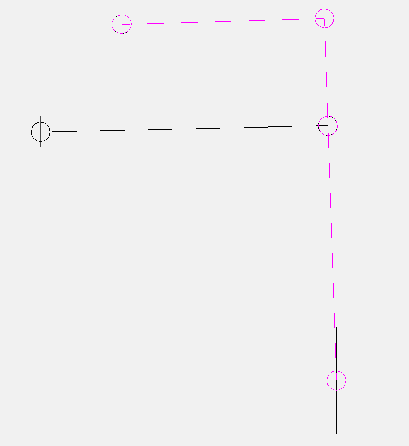
Example:
Looking for a straight four-bar linkage as a replacement for a sliding guide.
Question: Which dimensions are worth optimizing?
Search field calculation
A search field computation searches a defined value range for all parameters and filters out the parameter combinations with the best target function values. The goal of the search field computation is to find good starting points for the search step or the Newton method.
The values of the optimization parameters are either systematically varied with specified steps, or they are selected randomly (Monte Carlo method). Even if "coincidence" sounds like "unsystematic" or "inferior": the chance of getting close to a good solution with relatively little computational effort is fairly high.
With a small number of optimization parameters and parameter steps, systematic parameter variation is recommended. The total number of variants to be calculated is the product of all numbers of single parameter variants.
Example:
Parameter a should be varied from 0 to 100 with a step of 10 (11 single parameter variants), parameter b from 0 to 50 with step 10 (6 single parameter variants). The total number of calculations is then 6 x 11 = 66.
With a very large total number of computations, such large computation times arise that the search space is practically no longer systematically searchable. Then the Monte Carlo method is recommended.
The sliding search field calculation works like the search field calculation, but with the variable center of the search area. As soon as a new best solution is found, this solution is the new center of the search area.
If the target function value of the current solution is better than a predefinable limit value, the widths of the search ranges are narrowed for all parameters with the same, likewise predefinable factor, so that the optimization near the optimum becomes more accurate!
Search step optimization
The search step optimization optimizes all parameters in such a way that the function value of a scalar total target function becomes optimal starting from a specified starting vector.
It is suitable for all optimization tasks.
The number and nature of the target functions is arbitrary.
The search step optimization requires a lot of computing time and only finds local optima.
The parameters x are enlarged and reduced one by one by a small delta.
The parameter value (x-delta, x or x + delta) with the best target function value is taken as reference for the next optimization step.
This loop finishes when the target function values no longer improve.
Subsequently, the parameters are varied with reduced increments until the increments fall below predetermined limits.
Composite optimizations
To make numerical optimizations more stable and faster, we logically break them down into nested sub-optimizations.
Syntax:
OPTIMIZATION = EXPRESSION
OPTIMIZATION = EXPRESSION OPTIMIZATION
EXPRESSION = NAME
EXPRESSION = NAME (OPTIMIZATION)
Example:
A rocker arm should emulate a transfer function of given shape as accurately as possible. In any case, an output swing angle of 60 degrees should be maintained.
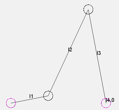
Overall, crank length l1, coupling length l2 and frame length l4 should be varied.
The rocker length l3 is set to a fixed value. It normalizes the size of the mechanism. Simply scaling the entire mechanism would not change the transfer function.
For a given coupling and frame length, the rocker angle range is significantly dependent on the crank length.
In an inner optimization loop, the crank length should therefore be optimized to the 60 degree oscillation angle. For this purpose, the fast Newton method is preferred, because there is always an exact solution for this subtask, as long as the linkage remains fit to run.
In an outer loop, the search field calculation and then the search step method optimize coupling and frame length to the best possible compliance with the shape of the transmission function. There is no exact solution for this external optimization.
The structure of this optimization looks like this:
Searchfield_l2_l4(Newton_l1),Searchfield_l2_l4(Newton_l1)
To the homepage of Nolte NC-Kurventechnik GmbH
Start Mechanisms Kinematics CamDesign Indexing Servo+PLC MotionDesign Training Service CamCalculation Software Imprint PrivacyPolicy
Structural Graphical Numerical Newton Parameters TargetFunction RelevantParameters SearchField SearchStep CombinedOptimizations LinearGuideExample
11/06/21
• Software OPTIMUS MOTUS ® /
DasNolte ®
• All types of Cam Calculations
• Performance Optimizations
• Trainings and consulting
• App and Software Development
• PLC Motion Software
Cams, Mechanisms, Motion Design. Faster Machines. Since 1965.
